|
When installing the MAFT Pro certain functions formerly handled by the TCCS (aka ECU) are now handled by the MAFT Pro and the ECU is fed air flow data that's already been adjusted for these conditions. In this case I am specifically referring to the air density changes due to temperature changes and altitude. The fact that the MAFT Pro will be handling these calculations isn't an issue in itself so long as the TCCS is fed a valid static (not changing) signal. The problem is further complicated if the TCCS doesn't receive these signals within a certain period after powering up. There are two ways of handing this.
**In the case of the 7M-GE (non-turbo) one of these outputs is used to supply the air flow data, so there remains only one programmable voltage output at your disposal. |
|
 VC supplies 5v, this is what feeds Vin in the above diagram. E2 is the sensor ground. If R1 and R2 (resistors) are of the same value the result at Vout would be one half of that supplied at Vin. |
|
For you turbo guys you want to put a 2.2K resistor between THA and E2. This will give the ECU an intake air temp of about 68ºF. This may be a little aggressive for those of you in hotter climates though, so keep thin in mind. If you want to tell the ECU something a little warmer you could use a resistor between 1.2K and 1.5K. You can reference the chart HERE if you want to see what the ECU is set to per an approximate amount of resistance. Then you would use a 1.2K resistor for R1 and a 2.7K resistor for R2 to supply HAC with a signal voltage of 3.46v. (The values shown in the diagram below are perfectly acceptable as well. They provide a signal of 3.41v.) 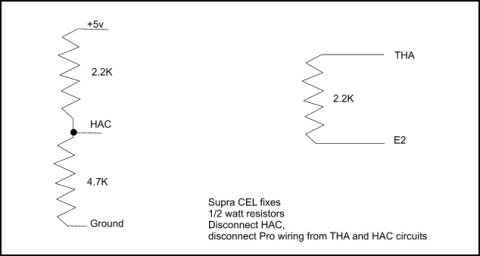 |
|
On the 7M-GE for THA you would use one 1.2K resistor for R1 and another 1.2K resistor for R2, this will supply your THA signal of 2.5v. You don't have a HAC sensor, so that's the end of the resistor fun... keep reading though, you're not in the clear. The next thing you need to do is to set up the MAFT Pro so it powers up BEFORE the TCCS (ECU). We'll do this with a relay and three diodes. The great thing about this method is that the ECU receives the required signals as soon as it starts (since the signals' voltage is supplied by the TCCS)... so, no more codes... well, you're still likely to get an air flow error code, so continue reading. |