|
MAFT Pro Wiring Diagrams Staged Wiring Diagrams Use only those specific to your installation. Preliminaries: 1) Powering the MAFT Pro via ACC and IGN More information is available here. Step 1 - Wiring the MAFT Pro to the ECU: Non-Turbo Turbo
Step 2 - Wiring the MAFT Pro to the Sensors: 2a) GM MAF (ex: If you're going to be running a GM LS-1 MAF) Current Version = 2.0
Step 3 - Wiring the MAFT Pro to the Wideband O2 Controller: 3a) Innovate Motorsports LC-1 Current Version = 2.0 Step 4 - Optional Features: 4a) Enhanced TPS (5.xx and newer only) Current Version = 2.0
|
|
OLD Diagrams - These are provided for reference purposes only. 7M-GE Specific: (7M-GTE follows then vehicle non-specific information) If you are going to be using a GM MAF (Mass Air Flow)
meter use this diagram:
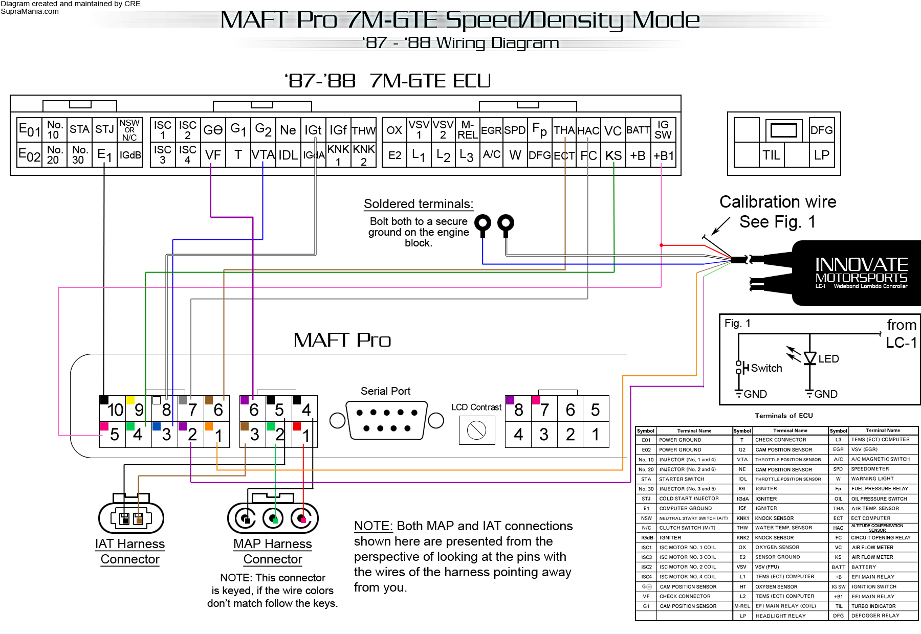
If you are going to be running Speed/Density (MAP
sensor w/IAT sensor) use this diagram: For more information on the FC circuit look HERE.
7M-GTE Specific: (non-specific information follows) Speed/Density (MAP sensor
w/IAT sensor)
|